|
Author
|
Topic: Radar sensor location
|
Randy Allen
|
 posted July 18, 2007 10:00 PM


Dave
Im installing a new 24 inch 4kw radome, and my two goals are preventing human irradiation and avoiding structural interference. (I understand and am not concerned with the range as limited by the height above water.)
Chapter 7, Figure 7-20 shows the near-field beam dimensions approximately equal to the antenna itself, with vertical dispersion occurring in the far-field.
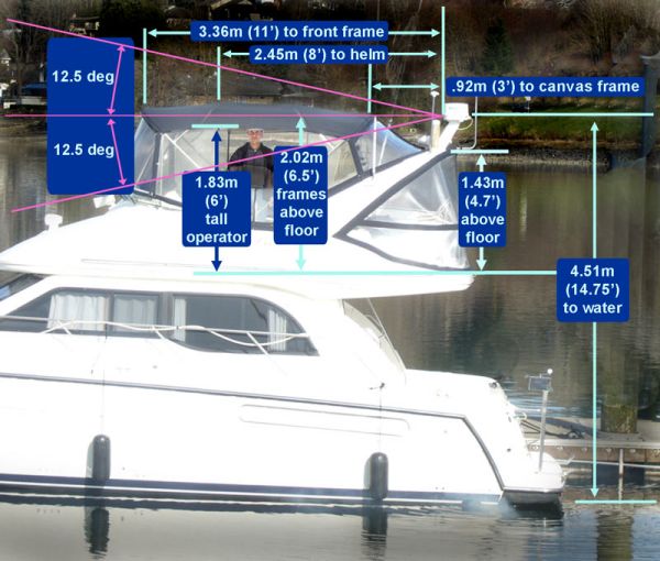
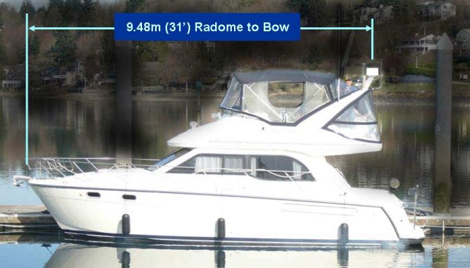
Photos of my existing system were taken from ashore at bridge level to maintain realistic perspective. My existing radome is 3 feet aft of, and essentially level with the metal canvas framework (structural interference), and is inches above the operators head (irradiation concern).
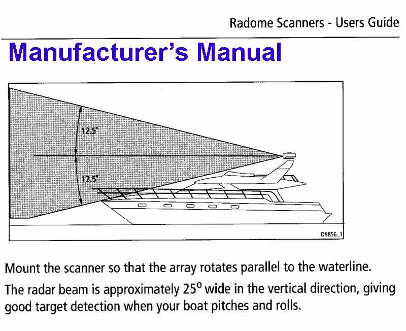
My manufacturers installation guide demands a very conservative installation compared to your figure 7-20. I attached the manufacturers illustration showing transmission through 25 degrees vertical. I inscribed 25 degree transmission lines on my side-view photo. Id need quite a high tower for a beam transmitted on the lower 12.5 degree line to clear the personnel on the bridge. (Their boat show rep suggested two to three feet clearance above the operator to the 12.5 deg line.)
To be safe how high does my new radar need to be above the operators body given my dimensions? Dave, if you operated this boat from the upper helm, where would you want the radome?
Let me thank you in advance for your very comprehensive and well-written text and this forum.
Randy Allen - Olympia, Wa
From: Olympia, Wa
|
|
David Burch
|
posted July 22, 2007 04:10 PM
Your pictures are posted which helps a lot. it does seem that the present level may be a bit low as is, if this pic is to scale. Your manufacturer suggestion is the standard one in use, though chances are the beam remains more focused for some time after leaving the antenna.
I should point out however that we do not have any actual installation proposals in the book. there are some schematic illustrations of installations showing estimated beam distribution, but none is an actual installation recommendation nor is any to scale. It could well be that the smaller the antenna the shorter the near field transition which brings some intensity lower than shown schematically relative to some arbitrary boat length.
You are doing now what has to be done. Namely figuring out for your own vessel the best arrangment.
One question might be, how often is one on the flying bridge with the radar on? Is there an actual read out at that station?
One thought occurs to me that i have not had before nor heard of trying, but i wonder what you would see on the radar screen if you placed someone at the topside helm and then slowly raised a large shovel spade over head. In other words, does it affect the radar display at all, and if so, at what elevation does it first appear. Just a thought.
From: Starpath, Seattle, WA
|
|
Randy Allen
|
posted July 28, 2007 06:05 AM
You were working Sunday afternoon on my answer - no rest!! Thanks for your reply. To answer your questions:
The boat's only display is located at the upper helm station. How often one operates the radar? Because of the poor installation, not very often. But that is the operating station. Being new at this I'm applying your suggestion to use the radar in good daylight visibility to learn to correlate visual with target images. Radiation safety is a concern (plus the interference of the bimini structure).
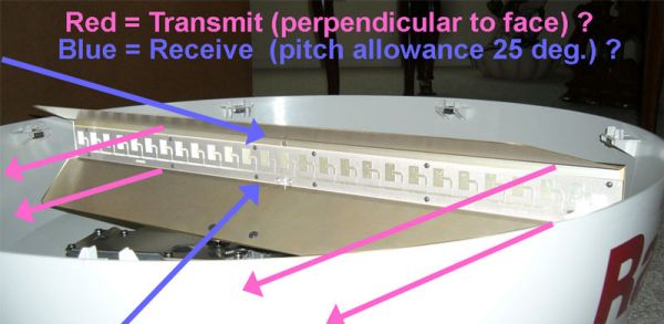
The photo of the radome's inner workings are from my new Raymarine RD424 (24 4kw) radome. (Not sure if you're sensitive to posting specific manufacturers.) Are the 25 degree reflectors only effective in receiving, not transmitting? Do they simply provide more gathering power (and allow for boat pitch)?
I appreciate the test you suggest using the shovel-spade. I'm considering placing the new radome atop some unobstructed playground equipment and running the shovel test using a battery. The display information gained would help determine the elevation required above the bimini framework.
Apparently the industrys installation guidelines are all conservative, but not entirely based upon the reality of the transmitted beams shape.
For safety, should I measure for microwave radiation? If you were me, would you consult your local microwave oven repair shop? Im wondering if a technician would appreciate an out-of-the-ordinary request to measure the radiation pattern from my radome. (Is his instrument calibrated to detect radar wavelength? Did I forget data from your book?) A plot could be developed of intensity vs. elevation below the radome centerline.
Would you go to this length to determine the geometry of a new mounting tower?
From: Olympia, Wa
|
|
David Burch
|
posted July 28, 2007 08:31 AM
The shields on the antenna are for limiting the vertical range of transmission. The reflected return beam is essentially a vertical wall of signal. I do not believe the antenna focusses any of the returned signal that it is catching.
i do not think that a micorwave cooker repair place will be able to provide information on marine radar... and i am not sure they have any devices for measuring the intensity. If you do run across any method, let us know.
Yes, the book does give a prescription for computing the near field length.
One suggestion would be to simply raise the antenna a foot or so, or alternatively to install the radar unit in the main cabin rather than above and then when steering from above to limit the use of the radar. Note that from the sitting position, the beam is likly well above head level.
I would also try the shovel experiement from the boat first as it might not work at all! -- which would then save a lot of trouble. Also i am not sure you are going to "see" the shovel on the radar screen at all but maybe just a blocking out of what was otherwise on the display.
From: Starpath, Seattle, WA
|
|
Randy Allen
|
posted August 02, 2007 04:32 AM
Many thanks for your reply -
Understand the comments about "seeing" the shovel rather than the shovel blocking the beam. (And scrap the playground test.) That makes me consider a wooden test fixture, with variable height, to mount the new radome on the boat. In this summer weather I can remove the canvas/windows and perform your shovel test under realistic conditions starting from your mounting suggestion and the calculated beam geometry. I would operate the radars one at a time.
I would mount the new system far to the side of the old system given my existing problem seeing forward objects. I would note any shadowing caused by the test mount blocking the existing beam.
I could learn the height required to display forward ATON and other targets (a big step.)
If my existing system revealed targets more consistently I might not be so gun-shy and driven to experiment. A worthwhile gain of information? Thanks again !
From: Olympia, Wa
|
|
|